
Continue exploring all facades and exterior design guides.
Unsealed transition joints between opaque walls, fenestration rough openings, and roof parapets cause concealed interstitial condensation, failed whole-building blower-door tests, and costly facade demolition. Designing durable building envelope systems requires treating the six-sided building enclosure—sub-slab foundation, opaque exterior walls, punched windows, curtain walls, and roofs—as a continuous environmental separator governed by four distinct physical control layers, verified from pre-design through post-occupancy under ASTM E2813 Building Enclosure Commissioning (BECx).
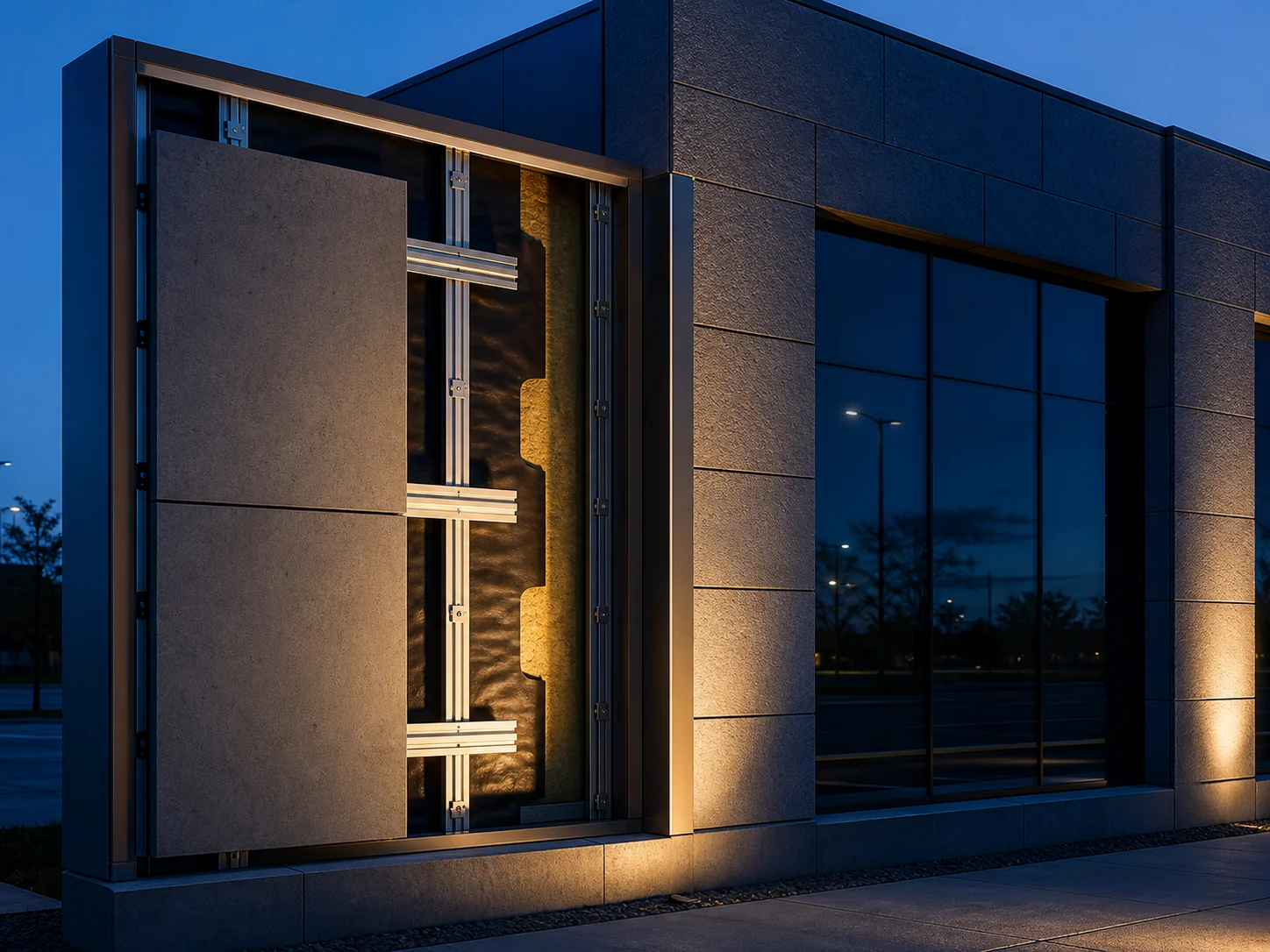
While exterior cladding panels establish the architectural profile of facades and exterior design, the visible cladding screen is only the first weather-shedding layer. In high-performance commercial and institutional enclosures, long-term moisture durability and thermal efficiency depend on maintaining uninterrupted continuity across the backup water-resistive barrier (WRB), air barrier system (AB), water vapor retarder (ASTM E96), and outboard continuous insulation (CI).
Swipe sideways to see the other columns. The first column stays visible.
| Control Layer (Ranked by Physical Criticality) | Primary Physical Function | Governing Standards & Code Sections | Optimal Plane in a Drained Rainscreen (“Perfect Wall”) | Dominant Interface Failure Mode | CD Drawing Review & Field QA Check |
|---|---|---|---|---|---|
1. Bulk Water Control Layer (WRB & Drainage Cavity) |
Sheds rainwater, meltwater, and wind-driven rain; drains incidental water back to the exterior | IBC Chapter 14, EPA 402-F-13053, ASTM E1105, AAMA 501.2 |
Exterior face of structural backup wall behind a >= 3/16–3/8 in. (5–10 mm) drained/vented airspace and shingle-lapped flashings |
Reverse-lapped head flashings, omitted sill pan end dams, or blocked weep slots trapping hydrostatic water | Trace gravity drainage paths and verify >= 2 in. upturned end dams and rear back dams on all rough-opening sill pans |
2. Air Control Layer (Air Barrier System) |
Stops convective air infiltration and exfiltration driven by wind, stack buoyancy, and HVAC fans | IECC C402.5, ASHRAE 90.1 §5.4.3.1, ASTM E2178, ASTM E2357, ASTM E779, ASTM E1186 |
Co-located with the WRB on the exterior face of the structural backup wall across all 6 enclosure sides |
Disconnected transition membranes at curtain wall mullions, open parapet framing cores, and unsealed interior window heels | Verify 3-tier 75 Pa limits (0.004 / 0.04 / 0.40 cfm/ft²), ASTM D4541 pull-off adhesion (>= 16 psi), and ASTM E779 fan testing |
3. Vapor Control Layer (Vapor Retarder) |
Controls molecular water vapor diffusion to prevent interstitial condensation while allowing drying | ASTM E96 (Procedures A & B), IBC §1404.3, ASHRAE Standard 160 |
Co-located with the air/water barrier inboard of exterior continuous insulation (CI), or tuned to climate vapor drive |
Specifying Class I (<= 0.1 perm) membranes on both sides of a stud cavity (“double vapor barrier”) or on the cold side of batt insulation |
Match ASTM E96 perm class (Class I, II, III, or Vapor-Open > 10 perms) to climate zone and outboard CI R-value ratio |
4. Thermal Control Layer (Continuous Insulation / CI) |
Slows conductive heat transfer and keeps the structural backup and air/vapor barrier above dew point | ASHRAE 90.1 §5.5, IECC C402, DOE Opaque Envelope |
Outboard of the air/water/vapor membrane on the structural backup wall, thermally isolating studs and slab edges | Continuous steel shelf angles, projecting concrete floor slabs, and uninsulated parapet stems creating linear thermal bridges | Detail structural thermal break shims at shelf angles and wrap parapet framing continuously to connect wall CI with roof insulation |
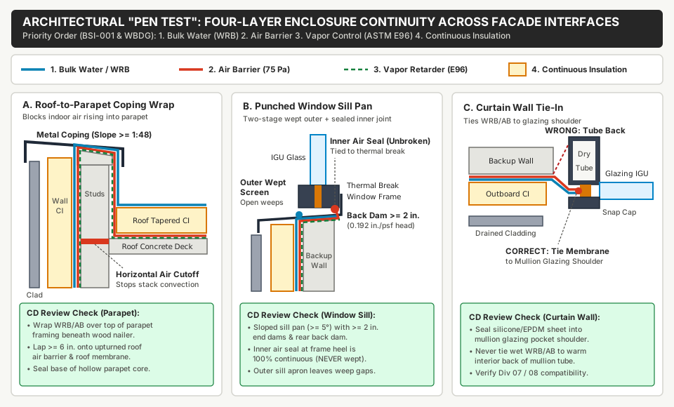
How to Execute the Four-Layer Continuity “Pen Test” on Architectural Drawings
In Building Science Corporation’s foundational guide BSI-001: The Perfect Wall and the WBDG Building Enclosure Design Guide, building envelope systems are evaluated by ranking the four environmental separators in strict order of failure severity: bulk water control first, air control second, vapor diffusion control third, and thermal control fourth. Liquid rain entry can rot substrates or corrode structural attachments within months; convective air leakage condenses interior moisture within a single heating or cooling season; diffusive vapor accumulation acts more slowly; and conductive thermal bridging penalizes energy use and local surface temperatures year-round.
The Co-Located “Perfect Wall” Arrangement
When comparing types of facade systems, the most resilient commercial wall assembly places the structural backup wall (cast-in-place concrete, concrete masonry units, or cold-formed steel studs with exterior glass-mat gypsum sheathing) completely inside the conditioned thermal and moisture boundary:
- Structural Backup Inboard: The backup wall carries dead, live, wind, and seismic loads in a stable indoor temperature and humidity environment.
- Co-Located Control Membrane (
WRB + AB + Vapor): A single continuous membrane—either a fluid-applied elastomeric membrane, a self-adhered sheet membrane, or a factory-laminated sheathing system with sealed joints—is applied directly to the exterior face of the structural backup wall to perform bulk water drainage, air barrier containment, and vapor control simultaneously. - Outboard Continuous Insulation (
CI): Rigid mineral wool, polyisocyanurate, or extruded polystyrene insulation is installed outboard of the membrane. Because 100% (or the majority) of the thermal resistance sits outside the membrane, the air and vapor control layer stays close to indoor room temperature across winter cold snaps and summer solar heating, eliminating thermal shock, UV degradation, and interstitial dew-point condensation on the backup sheathing. - Drained and Back-Ventilated Cladding Cavity: As detailed in our comparison of ventilated vs direct-applied cladding, an open
3/8 in.to1 in.(10–25 mm) air cavity behind the outer rainscreen cladding depressurizes wind-driven rain and provides convective drying.
Step-by-Step Drawing Review “Pen Test” Protocol
During Design Development (DD) and Construction Documents (CD) peer reviews under WBDG Building Enclosure Commissioning (BECx), reviewers audit wall sections (1-1/2 in. = 1 ft-0 in. and 3 in. = 1 ft-0 in. interface details) using four colored lines:
- Blue Solid Line (
Bulk Water / WRB & Flashing): Start at the foundation perimeter drainage plane and trace downward-overlapping shingle laps across through-wall flashings, window head flashings, sill pans, and weep exits. At every horizontal joint, verify that the upper membrane laps over the lower flashing leg so gravity never drives water behind a seam edge. - Red Solid Line (
Air Barrier System): Trace a continuous, unbroken six-sided boundary starting at the sub-slab vapor/air barrier, rising up the foundation wall into the exterior opaque wall air barrier, stepping inward through the flexible transition membrane to the window or curtain wall glazing plane, continuing across the glass and frame thermal break, stepping back to the upper wall air barrier, wrapping over the top of the structural parapet framing, and sealing into the primary roof air/vapor barrier. - Green Dashed Line (
Vapor Retarder): Verify theASTM E96perm rating of each layer along the red air-barrier line to confirm that no insulated cavity is trapped between two low-permeance (Class I <= 0.1 perm) layers. - Amber Shaded Band (
Continuous Thermal Insulation): Trace the continuous insulation plane from perimeter foundation slab insulation through opaque wallCI, across thermally broken window and curtain wall frames (aligning the glazing unit center-of-glass and frame thermal isolator in plane with wallCIwhere possible to minimize perimeter linear transmittanceΨ), and over the parapet into the tapered roof insulation.
Engineering Rule-of-Thumb: If you must lift your pen at any trade boundary—or if a control line terminates against an unsealed steel lintel, hollow CMU core, or un-plugged aluminum mullion tube—the drawing fails the continuity check and requires a dedicated transition detail specifying substrate preparation, primer, membrane lap width (
>= 2 in.to4 in.), sealant joint geometry (2:1width-to-depth ratio over closed-cell backer rod), and trade installation sequence.
Takeaway: Co-locate the water, air, and vapor control planes on the exterior face of the structural backup wall inboard of continuous insulation, and audit every section detail with the four-color continuity pen test before issuing bid documents.
Quantitative Air Barrier Tiers (75 Pa) and Vapor Permeance (ASTM E96) Pairing
According to WBDG Air Barrier Systems in Buildings, uncontrolled air leakage across small enclosure gaps transports 30 to 100 times more water vapor into a wall or roof assembly by convective airflow than molecular vapor diffusion drives through an intact material over the same period. Consequently, North American commercial energy codes (IECC Section C402.5 and ASHRAE Standard 90.1 Section 5.4.3.1), the Air Barrier Association of America (ABAA), and federal mandates (USACE UFGS 07 27 10.00 10) enforce a three-tier quantitative air leakage hierarchy measured at a reference pressure differential of 75 Pa (1.57 psf), equivalent to the stagnation pressure of an approximately 25 mph (40 km/h) wind.
Why Permissible Air Leakage Scales by 10× Across Three Tiers
A frequent specification error is copying the material air-permeance threshold (0.004 cfm/ft²) into a whole-building blower-door testing specification, or assuming that specifying an ASTM E2178 compliant membrane guarantees whole-building code compliance. In reality, allowable air leakage increases by one order of magnitude (10×) at each physical scale to account for joints, fasteners, penetrations, and multi-trade assembly transitions:
Swipe sideways to see the other columns. The first column stays visible.
| Performance Tier & Scale | Governing Test Standard | Maximum Air Leakage at 75 Pa (1.57 psf) |
Metric Limit at 75 Pa |
Specimen & Test Configuration | What This Tier Verifies (and Excludes) |
|---|---|---|---|---|---|
| Tier 1: Air Barrier Material | ASTM E2178 (Air Permeance of Building Materials) |
<= 0.004 cfm/ft² |
<= 0.02 L/(s·m²) |
1 m × 1 m continuous unpunctured membrane or board coupon tested in a lab chamber from 25 Pa to 300 Pa |
Verifies intrinsic material porosity only; excludes seams, fasteners, termination sealants, and rough openings |
| Tier 2: Air Barrier Assembly | ASTM E2357 (Air Leakage of Air Barrier Assemblies) |
<= 0.04 cfm/ft² (10× Tier 1) |
<= 0.20 L/(s·m²) |
Two 8 ft × 8 ft (2.4 m × 2.4 m) lab wall mockups (one opaque wall; one penetrated wall with a 3 ft × 3 ft window opening, pipes, brick ties, and outlet boxes) cycled under wind loads up to ±1,200 Pa (25 psf) |
Verifies that the complete manufacturer system—field membrane, lap sealant, transition strips, and brick-tie penetrations—survives wind-load deflection without tearing or unsealing |
| Tier 3A: Whole-Building Enclosure (Code Baseline) | ASTM E779 / ASTM E1827 / ASTM E3158 (IECC C402.5 & ASHRAE 90.1 §5.4.3.1) |
<= 0.40 cfm/ft² (10× Tier 2; 100× Tier 1) |
<= 2.0 L/(s·m²) |
Multi-point fan pressurization and depressurization (10–75 Pa) of the completed building normalized over the total 6-sided enclosure area (ft² of slab/floor + walls + roof) |
Verifies as-built whole-building airtightness across all roof-to-wall, window, louver, and foundation transitions |
| Tier 3B: High-Performance / Federal Whole-Building | ASTM E779 / ASTM E3158 (USACE UFGS 07 27 10.00 10) |
<= 0.25 cfm/ft² |
<= 1.25 L/(s·m²) |
Mandatory whole-building multi-point pressurization and depressurization test for U.S. Army Corps of Engineers (USACE), NAVFAC, and high-performance institutional facilities |
Enforces a 37.5% tighter whole-building envelope than baseline commercial code prior to beneficial occupancy |
| Component Sub-Tier: Fenestration & Curtain Walls | ASTM E283 (IECC Table C402.5.2 & ASHRAE 90.1) |
<= 0.06 cfm/ft² (fixed / curtain wall); <= 0.20 cfm/ft² (operable) |
<= 0.30 L/(s·m²) (fixed); <= 1.0 L/(s·m²) (operable) |
Accredited laboratory chamber test of a framed glazing assembly at 75 Pa (1.57 psf) or 300 Pa (6.24 psf) per NAFS |
Verifies factory frame gaskets and sash weatherstripping; excludes field rough-opening perimeter joints |
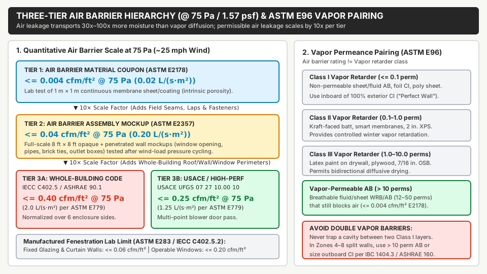
Water Vapor Permeance (ASTM E96) Pairing Rules
An air barrier and a vapor retarder perform entirely separate physical roles. Every building envelope system in IECC Climate Zones 1 through 8 requires a continuous air barrier (<= 0.004 cfm/ft² material permeance under ASTM E2178), but the water vapor permeance of that membrane—measured in perms (grains/(hr·ft²·in. Hg)) under ASTM E96 (Standard Test Methods for Water Vapor Transmission of Materials, Procedure A Dry Cup / Desiccant Method at 0–50% RH or Procedure B Wet Cup / Water Method at 50–100% RH)—must be selected based on wall insulation topology and climate zone (WBDG Moisture Management Strategies):
- Class I Vapor Retarder (
<= 0.1 perm): Essentially vapor-impermeable (e.g., rubberized-asphalt or butyl self-adhered sheet air barriers, non-permeable fluid-applied membranes, sheet polyethylene, aluminum foil-faced polyisocyanurate). - Class II Vapor Retarder (
0.1 perm < permeance <= 1.0 perm): Semi-impermeable (e.g., kraft-faced fiberglass batt, variable-permeance “smart” polyamide/ionomer membranes under dry winter conditions,1.5–2 in.extruded polystyrene). - Class III Vapor Retarder (
1.0 perm < permeance <= 10.0 perms): Semi-permeable (e.g., latex primer and paint over interior gypsum drywall, plywood,7/16 in.OSB sheathing). - Vapor-Permeable (Vapor-Open) Membrane (
> 10 perms): Allows unimpeded outward or inward diffusive drying (commercial vapor-permeable fluid-applied and spunbonded polyolefin WRB/air barrier membranes typically achieve12 to 50 permsunderASTM E96while maintaining<= 0.004 cfm/ft²airtightness underASTM E2178).
When reviewing Division 07 air barrier specifications against U.S. Department of Energy opaque envelope guidelines, enforce three hygrothermal pairing rules:
- 100% Outboard Continuous Insulation (No Stud-Cavity Insulation): When all thermal insulation sits outboard of the structural sheathing membrane and the steel/wood stud cavity contains no batt insulation, either a Class I vapor-impermeable (
<= 0.1 perm) or vapor-permeable (> 10 perms) membrane may be installed on the warm exterior face of the sheathing across Climate Zones 1–8 because the membrane surface remains above the indoor dew point. - Split-Insulated Walls in Heating & Mixed Climates (
IECC Zones 4–8): When fibrous batt insulation is placed inside the stud cavity alongside an interior Class I/II vapor retarder (or low-perm finish), specifying a Class I (<= 0.1 perm) exterior sheathing membrane creates a double vapor barrier unless the outboard continuous insulation (CI) satisfies the minimum R-value ratio inIBC Section 1404.3(or passes anASHRAE Standard 160transient hygrothermal analysis). If outboardCIis thin or absent, specify a vapor-permeable (> 10 perms) exterior air/water barrier so winter moisture in the stud cavity can dry outward. - Hot-Humid Cooling Climates (
IECC Zones 1A, 2A, 3A): Outdoor vapor pressure drives moisture inward toward air-conditioned spaces (72–75°F / 22–24°C). Never install an interior Class I vapor retarder, foil-backed gypsum board, or impermeable vinyl wallcovering on an exterior wall in Hot-Humid climates; keep the interior finish vapor-open (Class IIIlatex paint) so solar-driven inward moisture can dry harmlessly into the conditioned space.
Takeaway: Specify all three 75 Pa air-barrier tiers (ASTM E2178, ASTM E2357, and ASTM E779) in Division 01/07 documents, and verify ASTM E96 vapor permeance against cavity-vs-outboard insulation ratios so no wall assembly traps moisture between two Class I layers.
Critical Facade Transition Detailing Checklists for CD Peer Review
Most water intrusion and air-leakage failures occur not through the center of an opaque wall panel, but at multi-trade geometric transitions where combining facade materials requires passing control layers across Division 03 (concrete), Division 04 (masonry), Division 07 (waterproofing, air barriers, and roofing), and Division 08 (fenestration and curtain walls). Use the four engineering checklists below during 65% and 95% Construction Documents peer reviews.
1. Punched Window Rough Openings and Two-Stage Drained Sill Pans
Treating the exterior perimeter sealant bead around a punched window as a single face-sealed barrier violates rainscreen physics. If a pinhole opens in an exterior face seal while the interior window perimeter is left unsealed, wind stagnation pressure and indoor fan/stack depressurization pull exterior rainwater directly across the flat rough-opening sill into the stud wall.
According to WBDG Fenestration Systems and EPA Moisture Control Guidance (EPA 402-F-13053), every commercial punched window and storefront opening must use a two-stage drained joint over a three-dimensional sill pan flashing:
- Continuous Rough-Opening Air/Water Wrap: Wrap the opaque wall’s
WRB/ABor transition strip continuously into the rough-opening head, both jambs, and sloped sill substrate (>= 5°/1:12positive outward slope) prior to setting the window frame. - Three-Dimensional Sill Pan with Upturned End Dams and Rear Back Dam: Install a corrosion-resistant sheet-metal (stainless steel or anodized aluminum) or seamless fluid/pre-formed sill pan under the window frame featuring minimum
2.0 in.(50 mm) upturned end dams at both jambs and a continuous vertical rear back dam on the interior side of the window sill. - Hydrostatic Back-Dam Height Formula: During wind-driven rain or an
ASTM E1105chamber water test, negative interior air pressure raises a standing column of water inside the drained rough-opening trough. Because1.0 psf(47.9 Pa) of air pressure differential supports0.192 in.(4.88 mm) of water head:- Formula:
Minimum Back-Dam Height h_dam (in.) = (0.192 × P_test (psf)) + 0.50 in. safety margin - Worked Example: For a commercial window specified for an
ASTM E1105field water test atP_test = 10.0 psf(480 Pa), the static pressure differential alone supports a water column of0.192 × 10.0 = 1.92 in.(49 mm). A shallow1/2 in.(12 mm) upturned leg will overflow into the interior wall during testing; the detail must specify a minimum2.0 in.to2.5 in.(50–64 mm) rear back dam (or a baffled wept sill receptor rated for the test pressure).
- Formula:
- Inner Air/Vapor Seal (100% Continuous, Never Wept): Install closed-cell backer rod and elastomeric sealant (
ASTM C920Class 25/50) around all four sides of the interior heel of the window frame, aligned in plane with the window’s internal thermal break and sealed directly to the top of the sill pan back dam and jamb/head air barrier wrap. Because this inner seal stops air pressure from dropping across the outer cladding line, never weep or gap the interior air seal. - Outer Weather-Shedding Seal (Vented / Wept at Sill): At the exterior cladding and sill pan apron, leave open
2 in.(50 mm) weep slots every24 in.(600 mm) on center (or open baffled weep ports at quarter points) so water entering the rough opening drains freely outward. Set the window frame on discontinuous high-durometer EPDM or neoprene setting blocks (Shore A 80–90) positioned at quarter points so shims never dam horizontal drainage along the sill pan trough.
2. Stick and Unitized Curtain Wall Perimeter Tie-Ins (Division 07 ↔ Division 08)
As documented in WBDG Curtain Walls, the single most common detail error on commercial facades is drawing a schematic dashed line from the opaque wall’s air/water barrier to the warm interior back of a hollow aluminum curtain wall mullion—or conversely, out to the decorative snap-on exterior mullion cap.
- Align with the Glazing Pocket Shoulder (
Wet/Dry Boundary): In both captured stick-built and unitized aluminum curtain walls, the structural aluminum mullion tube behind the glazing pocket is dry and interior; only the shallow glazing pocket / pressure-plate gasket zone at the mullion shoulder (in line with the polyamide/thermoset thermal isolator and insulating glass unit) is engineered to carry and weep water. The flexible elastomeric transition membrane (pre-cured silicone or EPDM sheet) must bridge from the opaque backup wall’sWRB/ABdirectly into a dedicated reglet track or wet-sealed gasket lug at the mullion glazing shoulder. - Install Transition Membranes Behind Anchor Clips: At perimeter slab edges and 90° inside/outside corners, sequence construction so the opaque wall sheathing,
WRB/AB, and flexible perimeter transition sheet are installed and tested before curtain wall deadload/windload steel anchor brackets are bolted to the structure, sealing fastener penetrations with butyl/silicone isolation pads perASTM E2357. - Detail Internal Mullion End Plugs and Marriage Seals: Require the curtain wall shop drawings to call out butter-sealed closed-cell silicone/neoprene internal mullion end plugs at sill/head terminations and splice-sleeve marriage seals at unitized stack joints so air and water cannot bypass the perimeter transition membrane by traveling vertically inside hollow mullion extrusions.
- Verify Cross-Trade Chemical Compatibility: Modified-bitumen and asphaltic self-adhered wall membranes plasticize, bleed oil, and lose adhesion when placed in direct contact with neutral-cure silicone curtain wall weatherseals. Require a joint compatibility submittal signed by both the Division 07 air barrier manufacturer and Division 08 glazing sealant manufacturer confirming primer and transition-strip chemistry.
3. Roof-to-Parapet Framing and Coping Cap Wraps
According to WBDG Roofing Systems and EPA 402-F-13053, a roof parapet framed with cold-formed steel studs or hollow CMU behaves as an exposed chimney subjected to extreme solar heating, wind-driven rain, and winter freezing on both faces. If the exterior wall air barrier stops at the roof soffit or deck line while the roof membrane turns up only the interior parapet face, buoyant warm, humid indoor air convects upward inside the hollow parapet core and condenses heavily against the ice-cold underside of the sheet-metal coping cap—dripping back into top-floor ceilings and mimicking a roof leak.
- Over-the-Top Membrane Continuity: Extend the exterior wall’s
WRB/ABcontinuously up the exterior parapet sheathing, wrap completely over the top of the structural parapet framing (beneath the preservative-treated wood nailer/blocking), and lap at least6 in.(150 mm) down the roof side onto the upturned roof air/vapor retarder and primary roof membrane termination bar. - Horizontal Air and Fire Cutoff at the Roof Deck Plane: Across hollow steel stud or CMU parapet framing, detail a continuous horizontal sheet-metal closure, mineral wool fire/thermal packing, and elastomeric air-barrier mastic at the structural roof deck level to isolate the parapet cavity from conditioned ceiling plenums.
- Sloped Sub-Coping Membrane Under
ANSI/SPRI ES-1Metal Coping: Slope the top parapet wood blocking at a minimum of1/4 in. per ft(2%/1:48) toward the roof drain side (never toward the architectural facade face), cover the blocking fully with a high-temperature self-adhered waterproof sub-coping membrane, and anchor the cleated sheet-metal coping cap (ANSI/SPRI ES-1wind-rated) with gasketed fasteners. - Parapet Thermal Bridge Mitigation: Wrap both vertical faces and the top of concrete or steel parapet stems with continuous insulation (
CI)—or install a structural thermal break pad at the roof deck line—so the parapet does not act as a linear cooling fin penetrating the roof thermal envelope.
4. Foundation-to-Wall Base Flashing and Projecting Slab Shelf Angles
- Base-of-Wall Shingle Lap: At the grade transition, lap the above-grade opaque wall
WRB/ABover (shingle-fashion, minimum4 in.to6 in./100–150 mm) the top termination of the below-grade foundation waterproofing membrane above a stainless-steel through-wall base flashing with open exterior weeps. - Shelf-Angle Structural Thermal Breaks: Where masonry veneer relief angles or projecting concrete balconies cross the exterior
CIplane, detail high-compressive-strength fiberglass-reinforced thermoset structural thermal break shims or discrete stand-off knife-plate brackets so the air barrier and continuous insulation run behind the continuous steel angle rail.
Takeaway: Audit every CD interface detail for four non-negotiables: a >= 2 in. back-dam window sill pan with an un-wept inner air seal, curtain wall transition sheets terminated at the mullion glazing shoulder, parapet membranes wrapped completely over the structural framing, and shingle-lapped base flashings.
Building Enclosure Commissioning (BECx) Workflow (ASTM E2813 & NIBS Guideline 3)
Under NIBS Guideline 3-2012 (Building Enclosure Commissioning Process BECx), ASTM E2813 (Standard Practice for Building Enclosure Commissioning), and ASTM E2947 (Standard Guide for Building Enclosure Commissioning), enclosure commissioning is a structured quality-assurance process spanning five project phases—from Pre-Design through post-occupancy operations. Rather than waiting until finishes are installed to troubleshoot leaks (a forensic scenario covered in our guide to building envelope problems and testing), BECx engages an independent Building Enclosure Commissioning Provider (BECxP) to verify that the Owner’s Project Requirements (OPR) are translated into buildable details and verified before close-in.
ASTM E2813 and NIBS Guideline 3 define two commissioning tiers—Fundamental BECx and Enhanced BECx (which also align with LEED v4 / v4.1 Building Life-Cycle Impact and Envelope Commissioning credits):
Swipe sideways to see the other columns. The first column stays visible.
Project Phase (ASTM E2813) |
Core BECx Deliverables & Activities |
Fundamental BECx Minimum Scope |
Enhanced BECx Expanded Scope |
Mandatory Hold Point / Gate Before Next Phase |
|---|---|---|---|---|
| 1. Pre-Design | Draft the Owner’s Project Requirements (OPR) defining quantitative airtightness, water resistance, thermal/condensation risk, acoustic, and service-life metrics |
BECxP onboarded no later than Design Development (DD); reviews existing OPR |
BECxP engaged during Pre-Design to co-author measurable OPR criteria (<= 0.40 or <= 0.25 cfm/ft² @ 75 Pa, ASTM E1105 test pressures) |
Owner and Architect sign off on quantitative OPR enclosure targets prior to locking schematic assemblies |
2. Design (SD / DD / CD) |
Verify Architect’s Basis of Design (BOD), perform independent 4-layer “pen test” drawing reviews, and write Division 01/07/08 BECx testing specifications |
Minimum 1 to 2 design peer reviews (DD and late CD) tracked in a formal BECx Issue Log |
Minimum 3 structured design peer reviews at 35% DD, 65% CD, and 95% CD, plus hygrothermal (ASHRAE 160) and thermal-bridge review |
Every open drawing discontinuity in the BECx Issue Log must be resolved on the 100% Construction Documents prior to bidding |
| 3. Pre-Construction | Audit cross-trade shop drawings (Div 03/04/07/08), review sealant compatibility letters, chair pre-installation meetings, and witness mockup testing |
Coordinated submittal review and first-installation in-situ benchmark review | Build and test a stand-alone jobsite or laboratory performance mockup (ASTM E283, ASTM E331/E1105, ASTM D4541) before field facade work |
Mockup must pass air, water, and adhesion testing (and incorporate any required detail revisions) before production cladding begins |
4. Construction (Field QA/QC) |
Execute pre-close-in field inspections, verify substrate moisture and wet-film thickness (mils), and witness quantitative diagnostic field tests |
Periodic site observations and representative field air/water testing (ASTM E1105, AAMA 501.2) |
Continuous milestone inspections plus comprehensive field testing (ASTM D4541, ASTM E1105, AAMA 501.2, ASTM E1186/C1060 IR, and ASTM E779 whole-building blower door) |
Formal BECx pre-close-in sign-off required before exterior CI/cladding covers the air barrier and before interior drywall conceals window perimeters |
| 5. Occupancy & Operations | Deliver the Building Enclosure Systems Manual, train facility O&M staff, and conduct pre-warranty-expiration review | Handover of test records, warranties, and maintenance schedules | Full Systems Manual plus a 10-month post-occupancy walkthrough and seasonal thermal/moisture audit prior to 1-year contractor warranty expiration | All post-occupancy sealant, drainage, or air-seal defects remediated and re-verified under contractor warranty |
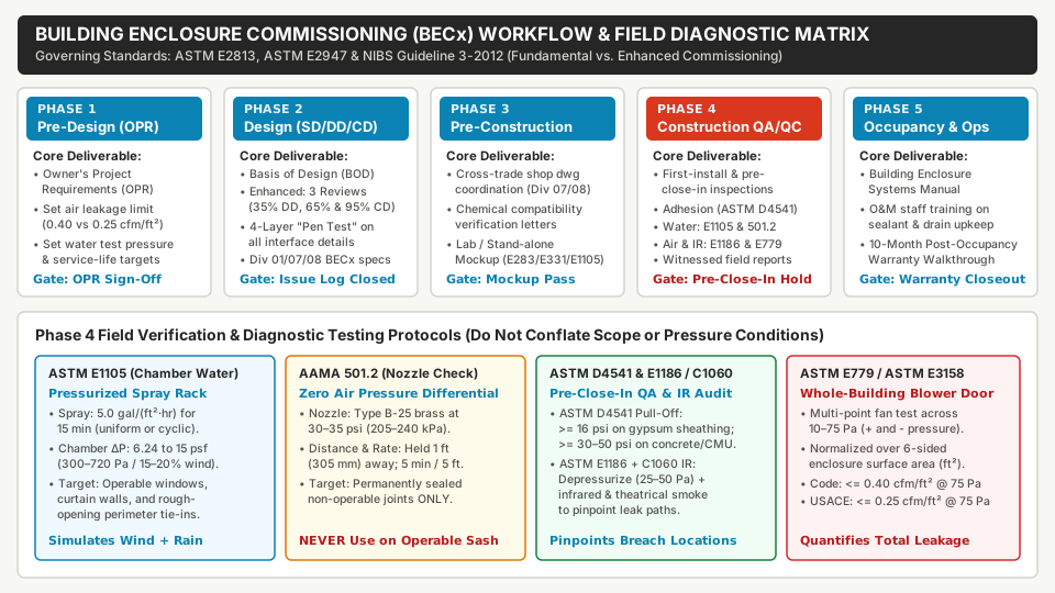
Takeaway: Engage the BECxP early enough to execute three design-phase continuity reviews (35% DD, 65% CD, 95% CD) and enforce mandatory pre-close-in hold points during construction before insulation, cladding, or drywall conceal transition joints.
Field Building Envelope Testing Protocols (ASTM E1105, AAMA 501.2, ASTM E779, ASTM E1186, ASTM D4541)
A rigorous building envelope testing specification pairs pre-close-in material and adhesion checks with installed-assembly water penetration tests and whole-building pressurization. Conflating two test methods—most commonly substituting an unpressurized AAMA 501.2 hose-nozzle check for an ASTM E1105 pressurized chamber test, or confusing qualitative ASTM E1186 leak localization with quantitative ASTM E779 air-leakage measurement—invalidates quality assurance.
Swipe sideways to see the other columns. The first column stays visible.
| Test Standard | Target Assembly & Scale | Specified Pressure, Flow, or Force Parameters | Primary Verification Purpose | Critical Procedural Boundary & Misuse Warning |
|---|---|---|---|---|
ASTM E1105 (Field Water Penetration by Static Air Pressure) |
Installed windows, curtain walls, doors, skylights, and rough-opening perimeter transitions | Calibrated spray rack at 5.0 U.S. gal/(ft²·hr) (3.4 L/(m²·min)) for 15 min (Procedure A uniform static or Procedure B three 5-min cyclic pulses) under 6.24 to 15.0 psf (300–720 Pa) interior negative chamber pressure |
Verifies that installed fenestration units, operable sash seals, sill pans, and perimeter transition joints resist simultaneous wind pressure and heavy rain | Gold-standard field water test for operable units and rainscreen perimeters. Schedule while interior rough-opening perimeters remain exposed before drywall installation |
AAMA 501.2 (Quality Assurance Hose-Nozzle Field Check) |
Permanently sealed, non-operable storefront, curtain wall, and sloped glazing joints ONLY | Type B-25 brass nozzle regulated to 30–35 psi (205–240 kPa) at nozzle intake, held 1 ft (305 mm) perpendicular to framing joint, swept slowly at 5 min per 5 linear ft (1.5 m) with 0 Pa air pressure differential |
Rapid localized QA check for gasket seating and wet-seal workmanship along fixed framing joints during curtain wall erection | NEVER use AAMA 501.2 on operable windows or doors: the high-velocity 35 psi water jet forces water past compression weathersweeps engineered for static air pressure (ASTM E1105) |
ASTM E779 / ASTM E1827 / ASTM E3158 |
Whole-building enclosure (or compartmentalized floor/zone) airtightness | Multi-point fan pressurization and depressurization from 10 Pa to 75 Pa, reported at 75 Pa (1.57 psf) per ft² of 6-sided enclosure surface area (<= 0.40 cfm/ft² IECC/ASHRAE; <= 0.25 cfm/ft² USACE) |
Quantifies total as-built air leakage rate (cfm/ft² or L/(s·m²)) across the complete six-sided building thermal envelope |
Outputs a single pass/fail leakage rate; does not identify individual leak locations unless paired with concurrent ASTM E1186 diagnostic scanning |
ASTM E1186 + ASTM C1060 |
Localized air-barrier breaches at parapets, soffits, window perimeters, and penetrations | Building or test chamber depressurized (25–50 Pa) while scanning with Infrared Thermography (ASTM C1060) (>= 10°C / 18°F ΔT or pressure-induced cold air streaks), theatrical fog / smoke pencils, or acoustic ultrasound |
Pinpoints exact air-leakage pathways so installers can seal breaches before close-in or prior to final ASTM E779 acceptance testing |
Qualitative localization tool only; cannot produce a code-compliance cfm/ft² leakage number |
ASTM D4541 (Pull-Off Strength of Coatings) |
Cured fluid-applied or self-adhered air/water barrier membranes on backup substrates | Portable hydraulic/pneumatic tester pulls a bonded 20 mm or 50 mm aluminum dolly perpendicular to membrane until failure. Pass: >= 16 psi (110 kPa) on glass-mat gypsum sheathing (cohesive core failure) or >= 30–50 psi on primed concrete/CMU |
Verifies substrate cleanliness, primer curing, and membrane bond strength before continuous insulation (CI) and cladding conceal the air barrier |
Test on early benchmark installations (first 500 ft²) so improperly primed or damp substrates are caught before full-elevation membrane application |
ASTM E283 & ASTM E331 / E547 |
Laboratory air leakage (E283) and water penetration (E331 static / E547 cyclic) of manufactured fenestration |
Lab chamber testing at 75 Pa / 300 Pa for air (<= 0.06 cfm/ft² fixed; <= 0.20 cfm/ft² operable) and 5.0 gal/(ft²·hr) under design pressure for water |
Confirms factory window/curtain wall extrusion and gasket engineering prior to shipping units to the jobsite | Lab product reports do not verify field installation quality, sill pan drainage, or perimeter transition seals—field ASTM E1105 testing is still required |
Sequencing Field Tests Before Concealment (First-Installation Benchmarks)
To prevent systemic rework across thousands of square feet of facade area, structure Division 01 commissioning specifications around first-installation benchmark holds:
- Substrate & Air Barrier Benchmark (
First 5%of Wall Area): Verify exterior sheathing fastener spacing, joint treatment, wet-film thickness (milsvia notched comb gauge for fluid-applied membranes), andASTM D4541pull-off adhesion (>= 16 psi) before authorizing continuous insulation installation. - First Installed Window & Curtain Wall Bay (
First 2–3 Units): PerformASTM E1105chamber water testing (coupled with chamber smoke/pressure checks perASTM E1186) on the first installed punched windows and initial curtain wall bay while the interior rough-opening perimeter is completely open and un-drywalled. If water breaches the outer gasket or transition tie-in, inspectors can directly observe whether the sill pan back dam contains the water column and whether the inner air seal holds at design pressure (6.24 to 15.0 psf). - Rolling
AAMA 501.2Curtain Wall Joint Checks: As stick or unitized curtain wall erection progresses up the building, executeAAMA 501.2(30–35 psiType B-25 brass nozzle at1 ftdistance,5 min per 5 linear ft) on fixed mullion-to-transom intersections and pressure-plate gaskets at5%,50%, and90%installation milestones—while keeping operable vents strictly segregated forASTM E1105chamber testing. - Pre-Occupancy Whole-Building
ASTM E779+ASTM E1186Blower-Door Verification: Once the roof-to-parapet wrap, exterior wall air barrier, and fenestration inner air seals are complete, run a preliminary depressurization scan with infrared thermography (ASTM C1060) and theatrical smoke (ASTM E1186) to seal stray mechanical penetrations or parapet gaps prior to the official witnessed multi-pointASTM E779/ASTM E3158test (<= 0.40 cfm/ft²or<= 0.25 cfm/ft²at75 Pa).
Takeaway: Sequence ASTM D4541 adhesion pulls and ASTM E1105 pressurized chamber water tests on the first installed facade bays before interior drywall or exterior cladding conceals the rough-opening transition plane, and reserve AAMA 501.2 nozzle checks strictly for permanently sealed non-operable joints.
Frequently asked questions
What is the difference between ASTM E2178, ASTM E2357, and ASTM E779 air barrier limits?
All three standards evaluate air movement at a reference pressure differential of 75 Pa (1.57 psf, equivalent to an approximately 25 mph wind), but each tests a different physical scale with a 10-fold increase in permissible leakage. ASTM E2178 measures intrinsic air permeance across a 1 m x 1 m material sheet or coating coupon (<= 0.004 cfm/ft² or 0.02 L/(s·m²)). ASTM E2357 measures air leakage across full-scale 8 ft x 8 ft wall assembly mockups containing seams, fasteners, pipe penetrations, and a window rough opening before and after wind-load pressure cycling (<= 0.04 cfm/ft² or 0.20 L/(s·m²)). ASTM E779 (alongside ASTM E1827 and ASTM E3158) measures whole-building enclosure air leakage in the field via multi-point fan pressurization normalized over all six sides of the thermal envelope (<= 0.40 cfm/ft² under IECC Section C402.5 and ASHRAE 90.1 Section 5.4.3.1, or <= 0.25 cfm/ft² under USACE UFGS 07 27 10.00 10).
When should you specify ASTM E1105 instead of AAMA 501.2 for field water testing?
Specify ASTM E1105 whenever testing operable windows, glazed doors, pressure-equalized curtain walls, or window-to-wall perimeter transition joints under simulated wind-driven rain. ASTM E1105 seals an interior pressure chamber over the installed assembly to maintain a negative static air pressure differential (typically 6.24 to 15.0 psf / 300 to 720 Pa) while a calibrated spray rack applies 5.0 U.S. gal/(ft²·hr) of water for 15 minutes. By contrast, AAMA 501.2 uses a handheld Type B-25 brass nozzle at 30 to 35 psi held 1 ft from the exterior framing joint for 5 minutes per 5 linear feet with zero air pressure differential. AAMA 501.2 is strictly a diagnostic check for permanently sealed, non-operable storefront and curtain wall joints; applying a 35 psi nozzle jet to operable window sashes forces water past compression weatherstripping designed for static air pressure.
Why must curtain wall transition membranes connect at the mullion glazing shoulder rather than the back of the mullion?
In captured stick-built and unitized aluminum curtain walls, the structural mullion tube behind the thermal break and glazing pocket sits inside the dry, conditioned zone of the assembly. Only the shallow glazing pocket and pressure-plate zone at the outer shoulder of the mullion is engineered to collect and weep water to the exterior. If the opaque wall's water-resistive and air barrier (WRB/AB) membrane is adhered to the warm interior back of the hollow aluminum mullion, water draining down the opaque cavity wall is directed behind the curtain wall's primary water control plane, bypassing the thermal break and leaking into anchor penetrations and interior drywall returns.
How do you prevent condensation inside roof parapets on commercial buildings?
Platform-framed steel-stud and hollow-CMU parapets act as chimneys exposed to outdoor cold on both faces. If the exterior wall air barrier stops at the soffit or roof deck level while the roof membrane turns up only the roof side of the parapet, buoyant warm indoor air rises into the hollow parapet core and condenses against the cold underside of the sheet-metal coping cap. Prevent this by installing a sealed horizontal air/fire stop across the base of the parapet at the structural roof deck plane AND wrapping the exterior wall's WRB/air barrier continuously over the top of the structural parapet framing (beneath the sloped wood blocking and secondary sub-coping membrane) to lap at least 6 in. (150 mm) onto the upturned roof air/vapor barrier.
Does an air barrier membrane also act as a vapor barrier?
Not necessarily. Air barriers resist convective airflow under pressure differentials (<= 0.004 cfm/ft² at 75 Pa per ASTM E2178), whereas vapor retarders restrict molecular water vapor diffusion measured in perms under ASTM E96. Commercial air barrier membranes are manufactured in both vapor-impermeable (Class I <= 0.1 perm) and vapor-permeable (> 10 perms, often 12 to 50 perms) formulations. In cold and mixed climates (IECC Zones 4–8), a split-insulated stud wall with interior batt insulation and an interior Class I/II vapor retarder requires a vapor-permeable (> 10 perms) exterior air/water barrier unless sufficient outboard continuous insulation keeps the sheathing interface above the winter dew point per IBC Section 1404.3.
What is the difference between Fundamental and Enhanced Building Enclosure Commissioning (BECx)?
Under ASTM E2813 and NIBS Guideline 3-2012, Fundamental BECx requires engaging an independent Building Enclosure Commissioning Provider (BECxP) no later than Design Development (DD), performing at least one or two structured design peer reviews at DD and Construction Documents (CD), reviewing enclosure submittals, and witnessing representative construction field QA/QC testing. Enhanced BECx begins during Pre-Design to author quantitative Owner's Project Requirements (OPR), conducts a minimum of three formal design peer reviews (35% DD, 65% CD, and 95% CD), requires pre-construction laboratory or stand-alone jobsite performance mockups prior to production facade installation, expands field witness testing across all critical trade interfaces, and includes a 10-month post-occupancy warranty review.
Sources
- Building Enclosure Commissioning (BECx) — Whole Building Design Guide (WBDG) / National Institute of Building Sciences Accessed October 25, 2026.
- Air Barrier Systems in Buildings — Whole Building Design Guide (WBDG) / National Institute of Building Sciences Accessed October 25, 2026.
- BSI-001: The Perfect Wall — Building Science Corporation Accessed October 25, 2026.
- Moisture Control Guidance for Building Design, Construction and Maintenance (EPA 402-F-13053) — U.S. Environmental Protection Agency Accessed October 25, 2026.
- NIBS Guideline 3-2012: Building Enclosure Commissioning Process BECx — National Institute of Building Sciences (NIBS) Accessed October 25, 2026.
- Building Enclosure Design Guide (BEDG) — Whole Building Design Guide (WBDG) / National Institute of Building Sciences Accessed October 25, 2026.
- Moisture Management Strategies — Whole Building Design Guide (WBDG) / National Institute of Building Sciences Accessed October 25, 2026.
- Fenestration Systems — Whole Building Design Guide (WBDG) / National Institute of Building Sciences Accessed October 25, 2026.
- Curtain Walls — Whole Building Design Guide (WBDG) / National Institute of Building Sciences Accessed October 25, 2026.
- Opaque Envelope — U.S. Department of Energy, Building Technologies Office Accessed October 25, 2026.