Buying bedroom soundproof wall panels for a neighbor-noise problem can leave the transmission path untreated. Acoustic absorption reduces reflections inside the bedroom; a surface panel’s NRC does not set the shared wall’s STC.
Choose acoustic absorption for bedroom echo, and investigate the complete separating construction for soundproofing between rooms. The useful comparison is between two jobs: an exposed absorber face and a documented sound-isolating wall assembly. Ask where the disturbing sound starts, then request the report that measures that task. A panel sold as “sound dampening” may describe an absorption treatment; the label alone establishes neither a party-wall rating nor a reduction in the noise reaching your bed.
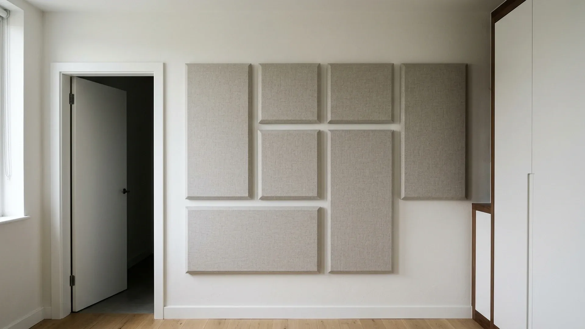
Example bedroom wall with fabric panels, a doorway and fixed joinery. These boundaries affect the usable face and attachment layout.
Which construction addresses the bedroom problem?
An absorption finish addresses reflected sound; a sound-isolation assembly addresses transmission through the room boundary. Keep those objectives separate when comparing the following options.
Swipe sideways to see the other columns. The first column stays visible.
| Option | Evidence to compare | Bedroom decision | Dominant Failure Mode & Prevention |
|---|---|---|---|
| Surface absorption panels | C423 absorption report, frequency data and E795 mounting description | Candidate for echo during speech, calls or listening | A decorative face is mistaken for a separating wall; require transmission evidence before accepting an isolation claim |
| Gypsum layers on a documented resilient-channel wall construction | Complete assembly detail and applicable E90 transmission report with E413 STC | Candidate construction approach when the separating wall is the relevant path | A rigid connection bypasses the resilient layer; follow the documented attachment detail and inspect junctions before closing |
| Isolation construction followed by an absorption finish | Separate transmission and absorption evidence | Consider when incoming noise and indoor reflections are both problems | Finish fixings or service alterations conflict with the assembly; coordinate attachments before installation |
The assembly approach above is documented in CGC’s Acoustical Assemblies guide, particularly the wood-framed details on printed page 28 and wall design guidance on pages 36–37. It is a construction family to investigate, rather than a specified retrofit for an unknown existing party wall.
What do STC and NRC establish?
STC describes sound insulation under a named transmission test; NRC summarizes absorption. Neither number can stand in for the other.
ASTM E90, scope 1.1–1.2, measures airborne transmission loss through a laboratory specimen. ASTM E413, scope 1.3.1, identifies the E90-derived single-number rating as STC. Match a quoted STC to the complete tested partition, including its framing, board layers, cavity and attachments.
ASTM C423, scope 1.1, measures absorption through sound decay in a reverberation room. NRC is an absorption summary, not the fraction of all bedroom noise blocked. ASTM E795, sections 4.1–4.3, explains why mounting matters and why some laboratory fixtures are unsuitable as installation details. Keep the backing, air space, exposed edges and frequency results with the panel description.
For the material shortlist, use the comparison of acoustic wall-panel types. This bedroom decision does not require another ranking of foam, felt or decorative slats.
When is a resilient-channel assembly worth investigating?
Investigate a documented assembly when the relevant path is transmission through the separating wall and alterations are feasible. CGC’s guide shows gypsum panels, resilient channels, cavity insulation and perimeter sealing as coordinated parts; its page 33 also illustrates an unwanted mechanical short circuit.
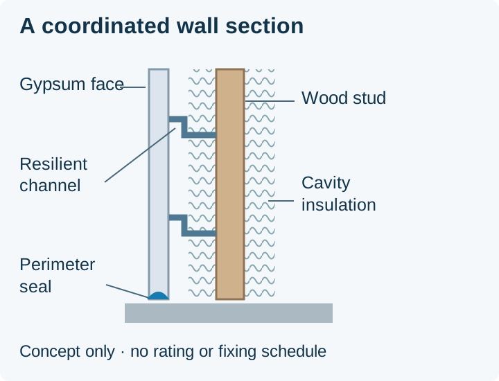
Schematic, not to scale. Original drawing of the component relationships in CGC SA200, printed page 28; no assembly rating or fastening schedule is assigned.
Do not turn that illustration into a shopping list of interchangeable layers. The guide’s component guidance on printed page 7 rejects unsupported substitutions. Record the existing wall, its junctions and the proposed build-out, then match a complete construction to the acoustic brief and applicable building requirements. Adding an unspecified membrane or changing the board arrangement does not inherit another assembly’s rating.
Rules-of-Thumb: If the available build-out minus the complete documented assembly build-out is less than 0 mm, under the measured bedroom layout, choose another documented assembly or revise the layout because the selected construction cannot fit unchanged. Do not remove a layer or bypass its resilient attachment merely to make it fit. This threshold checks dimensional feasibility, not acoustic performance.
How much wall face is available for absorption?
Count the usable face after openings and fixed joinery; a full wall elevation is not necessarily installable absorption area. The geometric calculation is:
A_usable = W × H − A_openings − A_joinery
W and H are wall width and height in meters; each area is in square meters. Exclusions must not overlap.
Worked example — assumed dimensions: assume a rectangular wall with width W = 4.0 m; assume height H = 2.5 m; assume openings occupy 2.0 m²; assume fixed joinery occupies 1.0 m²; and assume these exclusions do not overlap. Therefore A_usable = 4.0 × 2.5 − 2.0 − 1.0 = 7.0 m². This is an upper geometric allowance before panel layout and mounting constraints, not a recommended treatment quantity or a predicted STC improvement.
Use the panel placement and mounting guide to connect that allowance to the actual desk, listening position and attachment conditions.
What can make the finished bedroom disappoint?
Flanking paths and construction differences can undermine the isolation expected from a laboratory rating. E90 section 5.2 explains that laboratory testing suppresses paths that often exist in buildings; E413 section 4.2 also identifies construction errors and flanking as reasons for a lower building result.
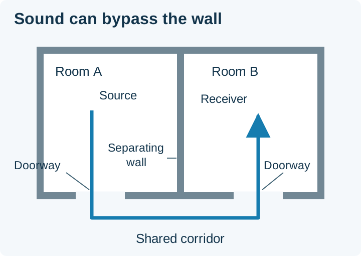
Schematic, not to scale. A doorway route bypasses the separating wall, following the doorway-placement principle in CGC SA200, printed page 32.
Hidden-cost note: Finishing the headboard wall before resolving its junctions and service openings can mean removing the new finish to inspect or repair the isolation construction. Use the placement and mounting survey guide to record attachments, access and removal constraints. Include access, reinstatement and the lost usable face in the scope; CGC’s printed pages 32–34 illustrate why the review extends beyond the middle of the wall.
A bass-heavy music complaint also needs more than a single-number comparison: E413 section 4.1 calls for frequency-band analysis for sources whose spectra differ substantially from its ordinary speech and television context. “Acoustic wall panels for home theater” is therefore a separate room brief, not evidence of bedroom isolation. If the source is outdoor traffic at the window, use the window STC versus OITC guide for that facade element.
Methods and sources
This comparison uses the public ASTM scopes and significance sections linked above, plus CGC’s published assembly and junction details. The area example uses stated assumptions and geometry; no product rating is inferred from it. Return to the interior finishes guide to coordinate the chosen construction with the room’s other surfaces.
Updated October 2026.
Sources
- ASTM E90-23 — laboratory airborne sound transmission loss — ASTM International Accessed October 19, 2026.
- ASTM E413-22 — classification for rating sound insulation — ASTM International Accessed October 19, 2026.
- ASTM C423-23e1 — reverberation-room sound absorption — ASTM International Accessed October 19, 2026.
- ASTM E795-23 — mounting specimens for absorption tests — ASTM International Accessed October 19, 2026.
- CGC Acoustical Assemblies — SA200 — CGC / USG Accessed October 19, 2026.