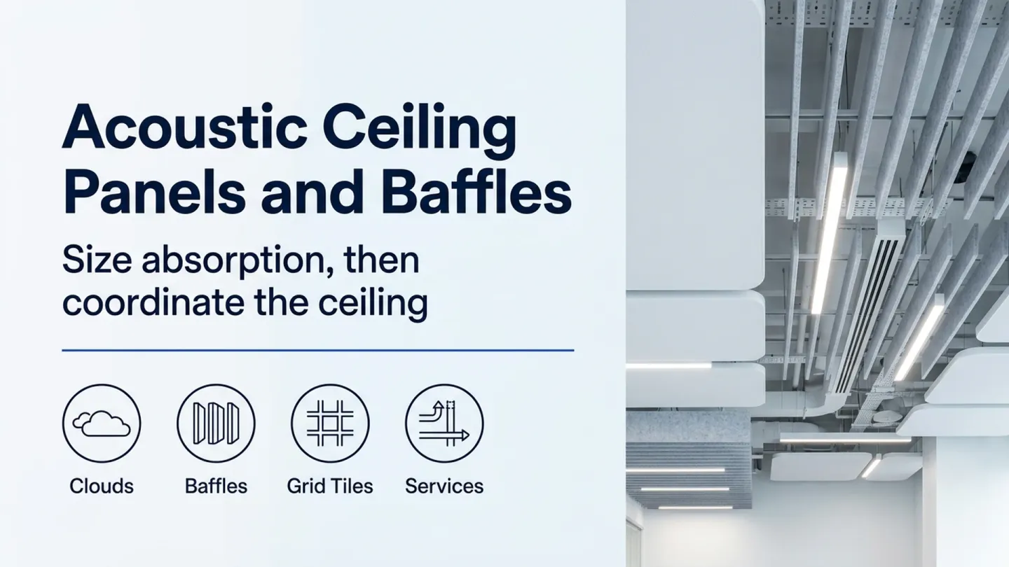
Acoustic ceiling panels and baffles can lose useful treatment area when lights and services displace the planned layout. Select clouds, baffles or lay-in tiles against an RT60 absorption budget, then check the coordinated ceiling arrangement before setting quantities.
Choose acoustic ceiling panels and baffles by the absorption the room needs and the space the completed service layout leaves available. Horizontal clouds suit island arrangements, vertical baffles suit open arrays, and acoustic ceiling tiles in a nominal 2 ft × 2 ft format suit a compatible grid. Compare tested arrangements rather than appearances or coverage percentages. An RT60 estimate needs room volume and equivalent absorption; the finished layout also needs resolved lights, air terminals, sprinklers, supports and maintenance access.
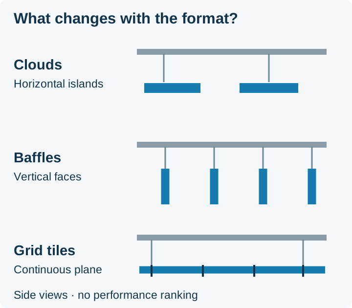
Schematic, not to scale. Clouds leave gaps between horizontal islands; baffles expose vertical faces; lay-in tiles form a grid plane. Format names follow Armstrong’s published ceiling arrangements.
Which ceiling format fits the intended layout?
Choose the format that can retain the required absorption while fitting the room and its services. There is no room-height cutoff that selects a format without those inputs.
Swipe sideways to see the other columns. The first column stays visible.
| Format | Layout role | Acoustic evidence to request | Dominant Failure Mode & Prevention |
|---|---|---|---|
| Horizontal clouds | Discrete islands below the deck, including above occupied zones | Absorption for the documented panel or array, with suspension and exposure identified | Islands collide with fixtures or lose area to cutouts; coordinate the plan and recalculate the retained treatment |
| Vertical baffles | Open rows with vertical faces and visible structure between them | Equivalent absorption per unit or tested array, including spacing and orientation | Counting both faces again overstates a result already measured for the whole object; use the report’s denominator |
| Lay-in ceiling tiles, including nominal 2 ft × 2 ft modules | A continuous grid plane with coordinated service modules | Frequency-band absorption and test mounting; compatible grid and edge details | Lights and grilles replace tiles counted as absorbers; calculate the actual tile area and retain access |
The nominal “2x2” module here means 2 ft × 2 ft. Armstrong’s Tips for Ceiling Installers, printed pages 7–8, describes this panel format and its border-grid layout. This names a module, not a performance class or a verified cut size. Confirm the selected tile’s actual dimensions and edge with the grid documentation. Direct-mounted panels are another possibility, but a suspension-mounted report does not establish their direct-mounted performance.
How should absorption reports be compared?
Compare like test arrangements and units before comparing ratings. ASTM C423, scope 1.1, covers absorption measurements for materials such as ceiling tiles and for objects. Its significance sections 5.3–5.5 explain why specimen edges and the difference between laboratory and room sound fields matter.
For surface coefficients, the absorption contribution at a frequency band is the exposed area multiplied by the applicable coefficient. For an object or array reported as equivalent absorption, use that reported quantity and its stated arrangement. Do not multiply a whole-object result by the number of exposed faces again.
The Armstrong auralization comparison illustrates this distinction by using NRC for some ceiling configurations and sabins per area for others. Its room, finishes and arrays define its examples; their RT results do not transfer to another room. Use full frequency data for the calculation rather than treating NRC as the absorption coefficient at every frequency.
For the broader difference between room absorption and sound isolation, start with the acoustic wall-treatment guide. A request for “sound dampening panels for ceiling” still needs that distinction if the actual complaint is sound from upstairs.
How much absorption does the RT60 target require?
Estimate the total equivalent absorption from the room volume and the agreed decay target, then subtract the absorption already present. The Sabine relation published in MIT’s room-acoustics notes, section 5.1, is:
T60 ≈ 0.161 V / A, so A_required ≈ 0.161 V / T_target.
T60 is the time in seconds for sound level to decay by 60 dB after the source stops; V is room volume in m³; A is equivalent absorption in m² sabins. The constant 0.161 has units of seconds per meter. Carry out the assessment by frequency band and keep occupancy and furnishing assumptions consistent. This statistical estimate presumes a sufficiently diffuse sound field; it does not resolve discrete reflections or low-frequency room modes.
Worked example — published office comparison: Armstrong’s auralization example describes a 5,000 ft² office, 100 ft × 50 ft, with 15 ft to the deck, drywall, windows on two sides and commercial carpet. It lists 3.4 s RT without treatment and 1.0 s with 260 white SoundScapes Blades, each 10 in × 94 in × 2 in, at 20% coverage. Its RT figures are averages of 500 and 1,000 Hz. Occupancy and the full suspension geometry are not specified on that page; these results remain a reference comparison for its described configurations.
For the same room volume, rearranging the Sabine relation gives A_blades / A_untreated ≈ T_untreated / T_blades = 3.4 / 1.0 = 3.4. Applied to the published average RT figures, this is an illustrative effective-absorption ratio; it is not a band-by-band design calculation or a blade rating. No new room dimensions, existing absorption or target are assumed.
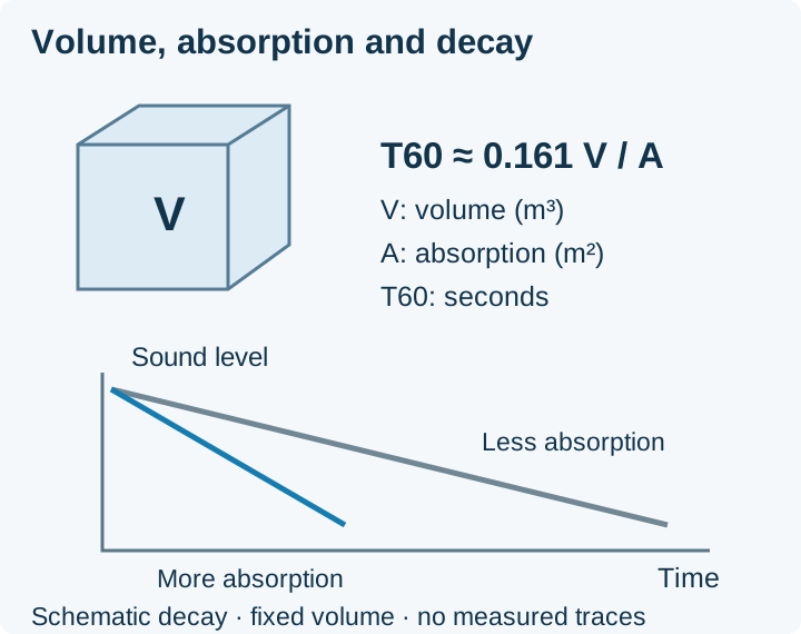
Schematic, not to scale. Original drawing from MIT session 18, section 5.1, equation 2. Decay lines show the relationship only; they are not measured traces.
For a project, calculate A_additional = A_required − A_existing separately at each assessment band. Supply the measured volume, agreed target, occupancy and furnishing state, then apply the selected system’s documented absorption and mounting. An average RT comparison cannot supply the missing band data.
Rules-of-Thumb: If A_available − A_required < 0 m² sabins at an assessment band under the agreed room and occupancy conditions, revise the documented treatment layout because the Sabine estimate remains above that band’s target. Recalculate after service exclusions; there is no universal coverage percentage.
How do the acoustic planes meet lights, diffusers and sprinklers?
Resolve those systems together on a reflected ceiling plan and the necessary sections before accepting the acoustic layout. Mark panel faces and edges, suspension points, fixture positions, air terminals and maintenance access on the same drawing.
Swipe sideways to see the other columns. The first column stays visible.
| Interface | What to resolve before fixing quantities | Document that closes the decision |
|---|---|---|
| Lights | Fixture position, optical obstruction, supports and maintenance route; show penetrations in absorption takeoffs | Selected luminaire and ceiling installation details |
| Supply diffusers and returns | Terminal location and the selected unit’s air-distribution and access requirements relative to clouds or baffle rows | Selected diffuser instructions and mechanical designer’s coordinated layout |
| Sprinklers and detection | Whether the proposed features obstruct distribution or activation; resolve the actual geometry | Fire-protection designer’s review using applicable requirements and selected system documents |
| Grid and suspension | Attachment to suitable support, service-module boundaries and removable access zones | Selected ceiling system’s instructions and coordinated support details |
Armstrong’s SoundScapes Shapes instructions, section 1.7, warn that these clouds can obstruct sprinkler distribution or delay activation and direct designers to fire-protection review. For the standard framed SoundScapes Shapes panels, section 4 permits lighting or sprinkler penetrations only with fixtures supported independently of the panel suspension. This permission excludes the SoundScapes Shapes 360° variant: section 6 prohibits cutting, drilling or altering those panels. Section 5 provides a specific lighting integration detail for the framed system. Those provisions do not establish a universal gap for other clouds, baffles or sprinklers.
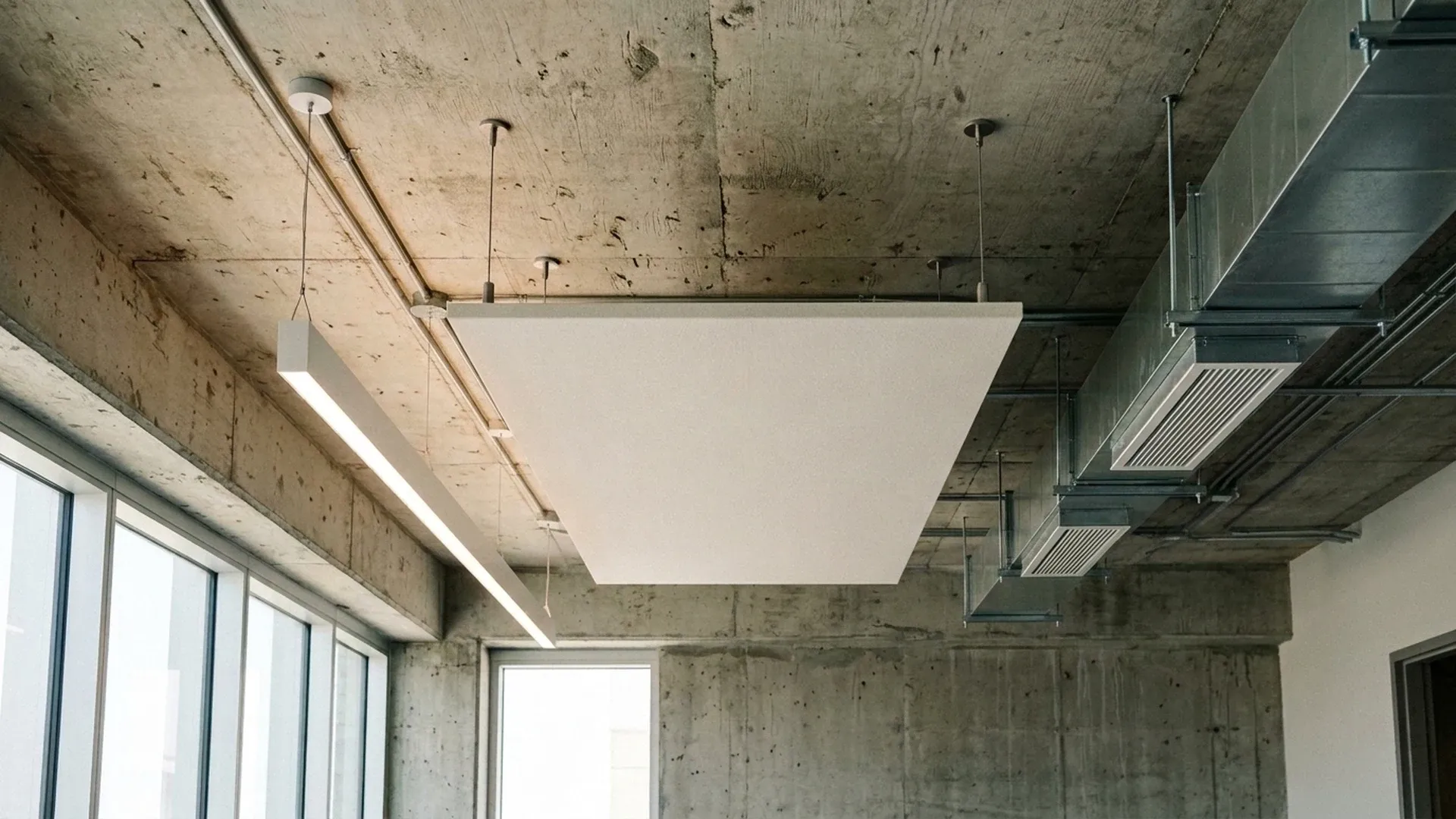
Example ceiling coordination elements: an acoustic island, a linear luminaire with separate suspension, and an air terminal. The view establishes no clearance or code approval.
Keep any required sprinkler or diffuser clearance as an unresolved dimension until the applicable design document establishes it. A gap drawn between baffles does not by itself confirm sprinkler performance or air distribution.
What hidden work changes the final selection?
Service exclusions can reduce the absorption that survives into the installed design. Revise the absorption budget whenever lights, grilles, access zones or permitted cutouts replace treatment; do not retain their former area or object count in the model.
Hidden-cost note: Moving a service after the ceiling is ordered can require replacement panels, revised suspension and another acoustic calculation. Record that rework alongside the lost absorption area when comparing layouts. Use the placement and mounting guide for the room survey and mounting record, then carry the ceiling-specific service decisions into the coordinated drawings.
Methods and sources
The selection method combines the public C423 scope, MIT’s published Sabine relation and the named manufacturer’s coordination instructions. The worked ratio uses Armstrong’s published office dimensions, configurations and average RT values; the general absorption budget uses MIT’s equation. Manufacturer example results do not predict another room. The interior finishes guide connects the ceiling decision with the other available room surfaces.
Updated October 2026.
Sources
- ASTM C423-23e1 — reverberation-room sound absorption — ASTM International Accessed October 19, 2026.
- Room acoustics and reverberation — session 18, section 5.1 — MIT OpenCourseWare Accessed October 19, 2026.
- SoundScapes Shapes — assembly and installation instructions, sections 1.7 and 4–6 — Armstrong Ceiling Solutions Accessed October 19, 2026.
- Auralization Tool — different ways of adding sound absorption — Armstrong Ceiling Solutions Accessed October 19, 2026.
- Tips for Ceiling Installers — 2 ft × 2 ft panel and border layout, pages 7–8 — Armstrong Ceilings Accessed October 19, 2026.